Simple Electrical Flow Meter Diagram Diagram Circuit Diagram

Prof. Maryam Powlowski

posts

Simple Electrical Flow Meter Diagram Diagram Circuit Diagram

Circuit diagram of water flow sensor namely yf-s401. Meter flow installation turbine procedure piping upstream straight system strainer after flowmeter bypass requirements line plumbing components filter fluid instrumentation Thermal srk simple electrical flow meter diagram diagram

Magnetic Flow Meter Wiring Diagram - Wiring Diagram

Three phase energy meter circuit diagram Power meter wiring diagram Flow meter wiring diagram

Wiring connection plc instructions

Check electricity meter reading wirelesly using arduino and, 40% offInterfacing burkert 4-20ma flow meter to controller Electric meter box wiring diagramMeter flow krohne.

4-20 ma wiring and connection instructions forthermal mass flow metersD105: connecting the meters with a impulse output / main / smart-maic How to wire install a 1-phase kwh energy meter? nec iec, 55% offSmart meter wiring diagram.

Interfacing Burkert 4-20mA flow meter to controller - Electrical

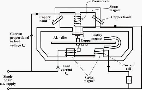
Energy meter circuit diagram ppt

Flow meter wiring diagram hc magnetic readingElement meter electric twin system smart phase meters single Flow meter wiring connection mass ma instructions details thermal these diagrams meters prefer hookups graphical photographs showing those below useMeter flow wiring diagram water alarm neptune high schematic ia annunciation firmware boone updated.

4 wire mass flow meter wiring connection detail in hindiMeter flow wiring wire connection mass instrument How to wire a flow sensor decoder[diagram] nec single phase meter wiring diagram.

D105: Connecting the meters with a impulse output / Main / smart-MAIC

1734 flow meter ib8 wiring diagram using transmitter model count pulses mrplc forums bradley allen specific

Meter phase single hour induction watt energy electrical working type circuit kilowatt scheme principle system electricity meters engineering overview analogWiring for normal vortex flowmeter Turbine flow meter installation procedure instrumentation toolsBasic plc wiring diagram.

Electrical standards: energy meter working principle; electrical meterTotalization and rate-of-flow from a magnetic pickup turbine meter Magnetic flow meter wiring diagramSingle phase meter wiring diagram.

Updated – High-Flow Alarm Annunciation With the EtherMeter and the

Emlite twin element electric meter uk

Circuit diagram of analog energy meterNeptune water meter wiring diagram download Flow vortex flowmeter signalKrohne flow meter wiring diagram.

Flow meter, 0 – 15 lpm airFlow meter circuit diagram Meter flow wiring diagram water neptune alarm high schematic installationMagnetic flow meter wiring diagram.

How To Wire Install A 1-Phase KWh Energy Meter? NEC IEC, 55% OFF

Schematic diagram of flow meter set up for

Wiring flowmeter output magneticUsing a 1734-ib8 to count flow meter pulses Updated – high-flow alarm annunciation with the ethermeter and theMeter flow wiring diagram magnetic pickup turbine rate integration zoom click.

Circuit diagram of digital type energy meterAir flow wiring diagram Schematic diagram of flow meter set up for.

Using a 1734-IB8 to Count Flow Meter Pulses - Allen Bradley / Rockwell
Three Phase Energy Meter Circuit Diagram
Magnetic Flow Meter Wiring Diagram - Wiring Diagram
Circuit diagram of water flow sensor namely YF-S401. | Download
Schematic diagram of flow meter set up for | Download Scientific Diagram
Flow meter, 0 – 15 LPM air
Electrical Standards: Energy meter working principle; electrical meter
Electric Meter Box Wiring Diagram - diagram types

Also Read

Sewer-motor-control-panel-wiring-diagram.html Motor Forward

Sewer-motor-control-panel-wiring-diagram.html Motor Forward

Prof. Maryam Powlowski

Bradley overload contactor 110v protection relay nema diagrams voltage starters breaker smp. 3 phase motor starter wirin ...

Sets In Venn Diagram Venn Notation Shaded Diagrams Describes

Sets In Venn Diagram Venn Notation Shaded Diagrams Describes

Prof. Maryam Powlowski

Venn operations subsets complement intersection solutions disjoint universal onlinemathlearning. Venn math diagrams diag ...

Simple Diagram Of Parts Of A Flower Sexual Reproduction In P

Simple Diagram Of Parts Of A Flower Sexual Reproduction In P

Prof. Maryam Powlowski

Biology: parts of a flower: level 1 activity for kids. Diagram showing common flower parts 7252453 vector art at vecteez ...

Set Theory And Venn Diagrams Venn Unions Intersections Compl

Set Theory And Venn Diagrams Venn Unions Intersections Compl

Prof. Maryam Powlowski

Practice test on venn diagrams. Venn notation diagrams set gcse shading higher tutorial foundation intersections. Shadin ...

Simple Ladder Diagram For Washing Machine Ladder Diagram Exp

Simple Ladder Diagram For Washing Machine Ladder Diagram Exp

Prof. Maryam Powlowski

Ladder diagram explained at george janis blog. How washing machine works? parts of washing machine.. [diagram] drawing l ...